EDM Modular Panels Standards.
Benefits of a Modular System
Self-contained Modules with specific protection and control equipment have been wildly accepted and in use in many electrical utilities throughout North America. Based on the advantages the modular system brings to the engineering and design of a substation, EDM has developed its own modular system with the following major advantages:
Rack Types
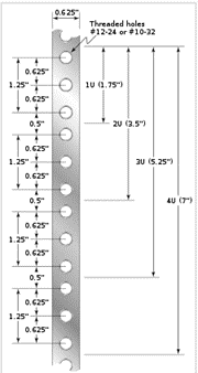
Equipment designed to be placed in a rack is typically described as rack-mount, rack-mount instrument, a rack mounted system, a rack mount chassis, sub rack, rack mountable, or occasionally simply shelf. The height of the electronic modules is also standardized as multiples of 1.75 inches (44.45 mm) or one rack unit or U (less commonly RU). The industry standard rack cabinet is 42U tall but can vary from each electrical utilities requirements.
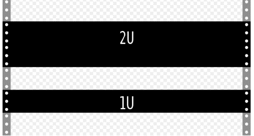
The size of a piece of rack-mounted equipment is frequently described as a number in "U". For example, one rack unit is often referred to as "1U", 2 rack units as "2U" and so on. A typical full size rack is 42U, which means it holds just over 6 feet of equipment, and a typical "half-height" rack would be 18-22U, or around 3 feet high. A front panel or filler panel in a rack is not an exact multiple of 1.75 inches (44.45 mm). To allow space between adjacent rack-mounted components for powder coating, a panel is 1⁄16 inch (0.031 inch or 0.79 mm) less in height than the full number of rack units would imply. Thus, a 1U front panel would be 1.719 inches (43.66 mm) high. If n is number of rack units, the formula for panel height is h = (1.750n − 0.031) inch = (44.45n − 0.79) mm.
The rack unit size is based on a standard rack specification as defined in EIA-310. (The Standard EIA-310-E is intended to provide overall design requirements for Cabinets, Panels, Racks and Subracks)
EDM Standard Protection Panels are 90"H x 24" W x 15" D Frame , rack type full EIA Pattern and come c/w custom clear plexiglass door (front), custom solid back door, 2-rsf85 rails (49U), 2 custom side panels and type FH3339 leveling legs (4 pcs set).
Module Types
Each module is designed for a specific function either protection, control, metering, or data acquisition. Each Module comes with and a module layout, bill of materials, ac/dc schematics, wiring and logic diagrams and nameplates for all devices within that module. All device connections associated with the main module device are wired out to terminal blocks located on the sides of the panels. The terminal blocks are run continuously down the side panels with internal wiring facing into the devices and external cables terminated on the outside of the terminal blocks. Module wiring drawings have a detailed BOM for all relays and auxiliary devices associated with that module.
Relay Module
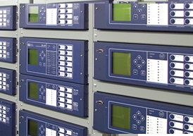
A Relay Module consists of a specific manufacture’s relay and its associated testing and isolating devices. The module shall contain a DC power supply for the relay and shall be fused at the module. The fuse shall be contained in a fuse holder type terminal block as specified on a Bill of Materials on the Module drawing. The module shall contain specific types of terminal blocks depending on the relay function connected to it. The following is a list of terminal blocks for specific functions associated with the relay:
Input Terminals Blocks – standard type terminal block as specified on a Bill of Materials on the Module drawing.
The following is a list of specific Auxiliary switching devices for specific functions associated with the relay: